Thursday, November 24, 2022

BREATHING AIR COMPRESSOR

 BREATHING AIR COMPRESSOR

Breathing air compressors are used to fill up SCBA and EEBD cylinders. Having the compressor on board determines the minimum number of SCBA cylinders on board as follows:


  • If the ship has a BA Compressor, there must be at least 1 charged spare cylinder for each SCBA set for Fire Fighterer Equipment and Safety Equipment. 
Ex: Total SCBA Set on board: 9
       Spare Required: 9
  •  If the ship does not have a BA Compressor, there must be at least 2 charged spare cylinder for each SCBA set for Fire Fighterer Equipment and Safety Equipment.

Ex: Total SCBA Set on board: 9
       Spare Required: 18

Please note that these cylinders shall be interchangeable.

For passanger ships carrying  more than 36 passangers or constructed on after 1 July 2010 ;

  • The source of emnergecy can be from main and energency switchboard or independently driven.
  • 60 l/min < BA Compressor filling capacity < 420 l/min or  
  • self-contained high-pressure storage systems of suitable pressure to recharge the breathing apparatus used on board, with a capacity of at least 1,200 l per required breathing apparatus, not to exceed 50,000 l of free air.'' (50,000 l / 1200 l = 41.7 ≈ 42 max  BA cylinders on board if this storage system is being used).


-SOLAS II-2/10

WORKING DIAGRAM OF BA COMPRESSOR

We will see below the working diagram of a BA Compressor. This is just a sample. Please see BA Compressor Manual on board your ship for the correct procedure. Every BA Compressor's system may slightly differ from each other.

Air flow diagram
Source: chrome-extension://efaidnbmnnnibpcajpcglclefindmkaj/http://www.erpbrandbev.nl/uploads/kcfinder/files/JuniorII-InstructionManual.pdf


  • Air is taken from air intake (1).
  • Air is compressed in three stages (3,4,5).
  • Between cylinders, there are two intercoolers, one after cooler and one seperator (6,7,8). The intercoolers and after cooler take the heat from the compressed air and let the temperature of the air drops which will increase the compression ratio of the next cylinder. The seperator extracts oil & water.
  • The cartridge (filter system) purifies the air compressed air (Hazmat gases such as CO & CO2 are filtered).
  • The purified compressed air comes at pressure maintaining valve. There are two options: 300 bar or 200 bar. One of them would be operational by user choice, which a valve is given. If you turn it clockwise, 300 bar in operation. When you turn it counter-clockwise, 200 bar is operational. The pressure switch over valve should be adjusted only when the compressor is not running and there is no pressure in the system.
BA Compressor Procedure


Please note that, the procedure of filling cylinders changes from one compressor to other. So check your compressor's manual before use. The sample above is just an example.

Parts of BA Compressor

Source: chrome-extension://efaidnbmnnnibpcajpcglclefindmkaj/http://www.erpbrandbev.nl/uploads/kcfinder/files/JuniorII-InstructionManual.pdf


Filter Assembly

Filter assembly consists of a cartridge, seperator chamber and timer (optional).

In the seperator chamber surrounding the cartridge, the oil and water is removed. During operation, this area has to be drained together with cartridge before and after operation and once every 15 minutes during operation by the  drain valves (1,2,3 in the photo left) .

The cartridge removes oil, water and hazmat gases (such as CO, CO2). Without the cartridge, the compressor is designed not to work such that the cartridge also provides a gas tight seal at the outlet of the filter system which allow the pressure built up. Without cartridge, the air will escape into the atmosphere and the pressure will not build up.
Filter lifespan is 4,000 loads at 330 bar or 35,000 loads at 225 bar working pressure difference or  1,000 for 330 bar units, and 8,750 for 225 bar units.. So that the maintenance records are vital. Fortunately, there is a timer on some of the cartridge.

The timer counts working time of compressor, cartridge pressure, temperature and air delivery rate of compressor.  It also displays operating hours, cartridge lifetime, and all maintenance due for the compressor. The timer may differ in property depending on the compressor if fitter. So that, please check the properties of timer of your compressor, if fitted, before use.

  • It is better to keep 50-80 bar pressure in the system after use to prevent moisture.
  • Always keep maintence records up dated.
  • Before any maintenace, depressurise the system.

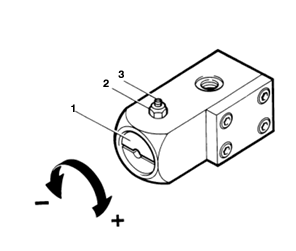
Pressure Maintaining Valve

Pressure maintaining valve is used to build up pressure. It is adjusted in factory. However, if it mulfunctions, you can adjust it as below:

  • Loose the nut (2)
  • Set screw (1)
  • Adjust screw by a screw driver (1)

Source: chrome-extension://efaidnbmnnnibpcajpcglclefindmkaj/http://www.erpbrandbev.nl/uploads/kcfinder/files/JuniorII-InstructionManual.pdf
Clockwise: Increase pressure
Counter Clockwise: Decrease pressure

Safety Valves

There are three safety valves at all three compression stages. However, what we are interested is the safety valve for third stage or final safety valve because it is mounted above the filer assembly (the other two ones are not visible) and it allows us to adjust final pressure. Actually, that safety valve is intented to be used to blow off pressure the exceesive pressure in case of mulfanctioning but in reality, I have observed that the engineers responsible for BA Compressor maintenace were adjusting final pressure simply by turning the knob at the top of the final safety valve.

Please note that some BA Compressor's final safety valves are factory sealed. So that only Maker's personnels are allowed to adjust.

Also, the final safety valves are two; one for 200 bar pressure outlet, and the other one is for 300 bar pressure outlet.

BA Compressor referenced: Bauer Junior II.

Tuesday, November 22, 2022

SELF CONTAINED BREATHING APPARATUS (SCBA)

SELF CONTAINED BREATHING APPARATUS (SCBA)

SCBA is used to fight with fire and enable us to enter into enclosed spaces where there is less oxygen.

Basically, there are two types of SCBAs; Closed-Circuit and Open Circuit. I will be focusing on more Open Circuit System since it is the most common type on board ships.

1. Closed Circuit SCBA               

  • These are also known as ''rebreather''.           
  • The exhaled gas is filtered and recirculated.
  • It allows more working time.
  • However, these are heavier.
2. Open Circuit SCBA

  • The air to breathe is stored in the cylinder.
  • The compressed air is passed 1st stage reducer where presure is reduced to medium pressure. Another branch of pipeline from the cylinder goes directly to the pressure gauge and Warning Device without any reduction in pressure.
  • Thereafter, the medium-pressured air is passed the 2nd stage reducer (a.k.a. Lung Demand Valve (LDV)) where pressure is redeced down to slightly above the ambient pressure.
  • The exhaled is is vented out to the environment from the mask.


BLOCK DIAGRAM OF OPEN CIRCUIT SCBA


Components of Open-Circuit SCBA


1. BA Cylinders

There are two types of BA Cylinders, steel and carbon-composite cylinders.

Steel BA cylinders are commonly used. They shall be hydro-tested at least once every 5 years (MSC Circ.1432)

Carbon Compsosite Cylinders consist of a alimunium liner over carbon fibers. These may be accepted by Administration if the followings are satisfied:
  • Max. charging rate: 27 bar/minute
  • If the cylinder is abrased or cut damaged to the carbon composite layer, it must be rendered as unserviceable.
  • There must be label on the cylinder that displays vital safety information and should be clearly marked.
  • Cylinders should be provided with a suitable protective cover for better protection against contact damage which should be removed prior to each charging for visual check.
  • They are subject to hydrostatic test as per Administration requirement.
 MSC Circ. 1432, MSIS 12 Chapter 9

Draeger Carbon-Composite Cylinder 
Source: chrome-extension://efaidnbmnnnibpcajpcglclefindmkaj/https://www.draeger.com/Products/Content/compressed-air-breathing-cylinders-all-pi-9105727-en-master.pdf

2. First Stage Regulator 

The working principle is the same with First Stage Regulator in EEBD. 

When the clinder is turned on, high pressure air will start to flow to the valve seat. When air is passed after the spring, the air accumulated between low pressure side of the pipeline and LDV will trigger the spring to close the valve.
Spring load is adjusted by maker.
Outlet pressure < spring load force: Valve Opens (spring in neutral postion) - air flows.
Outlet pressure> spring load force: Valve closes (spring is compressed) - air stops.

First Stage Regulator of SCBA


3. Warning Device

It shall be activated automatically  and warn that air in the cylinder is reduced to no less that 200 litres
( at around 55 +/- 5 barg - red rection at pressure gauge) (FFS Code 2.1.2).

 (200 l) / (40 l/min) = 5 minutes. That means, if warning device is activated, we must understand that aprroximately 5 minute remains to go!


4. Lung Demand Valve (LDV)

LDV is also known as ''Second Stage Regulator'' which decreases medium pressure to slightly above the atmospheric pressure. LDVs are activated by breathe of user and/or purge button.
LDV opeartion is automated depending on the face mask pressure. If we asssume that there is no leak in the face mask, user breathes govern the Lung Demand Valve operation.
The activation of LDV can be either ''Negative LDV'' or ''Positive LDV''.


  • In Negative LDV operation, LDV activates the flow when the pressure in the fack mask is reduced below ambient pressure. In case of a leak in the face mask, the hazardous gas may be inhaled.
  • The Postive LDV relies on the principle that face mask pressure is kept as always slightly above the atmospheric pressure. In case of a leak in the face mask, the cylinder will run off easily to try keeping the face mask pressure above the atmospheric pressure at all times.
Please see the video below the working of Positive Pressure LDV. 


PARTS OF LDV
Source: https://www.draeger.com/en_aunz/Products/PSS-Lung-Demand-Valve-LDV

5. Reset Button and Purge Button

Donning/Doffing button, also known as Reset Button is to cut air supply during donning or doffing.

Purge button activates air flow. It is used to supply air to the user if the user's hardy breathing or to purge the air remaining in the line when cylinder vavle is closed.

Some LDVs are also equipped with ''By-Pass Button''. This button is used to by-pass the LDV and give medium supply to the face mask in case LDV mulfanctions.

Donning Procedure of SCBA

Press OFF button (red) to cut off air supply to the facemask. Hear ''click''sound.


Pressure Test


Open cylinder valve and close.Check for the pressure. 

The pressure range should be 270-330 barg.

Leak Test

·         Wait for 1 minute.

·         Within 1 min, the pressure should not drop more than 20 barg.


Warning Sound Test

Disconnect facemask from second stage regulator.

Breath in the exit port and let the pressure drop slowly (Adjust pressure drop by blocking exit port by your hand).

The warning signal should be heard at around 50 barg.


  • Face Mask Seal Test
       Wear face mask.

                      Disconnect 2nd stage regulator.

             Plug in the end tube with your finger and breath in.


       The face mask should create vacuum over your face.


The donning test procedure above is just a sample. Please check your SCBA Manual for the correct procedure.

Some Important Rules Related with SCBAs

BAs shall be Self Closing type for which volume of contained air in the cylinder shall be at least 1200 l or be functioning of at least 30 min. ((1200 l)/(40 l/min) = 30 min))

SCBA shall be fitted with an audible and a usual or other device which will alert the user before volume of the air in the cylinder has been reduced to no less than 200 l. (This warning device simply consists of a whistle. However, there is also PASS Device (Personal Alert Safety System) which is electronic equipment and able to sense the motion of the user. ıf no motion is detected for 30 seconds, the alarm is generated. As you understand it is an advanced device and rarely seen on board ships.)

-FFS Code 2.1.2

Thursday, November 17, 2022

EMERGENCY ESCAPE BREATHING DEVICE (EEBD)

                      EMERGENCY ESCAPE BREATHING DEVICE (EEBD)

EEBD is a part of fire fighting equipment by SOLAS II-2/4.3 ''Espcape'' section and the basic technical requirements are given in  Fire Safety System Code (FSS Code 2.2). The above standards are applied depending on the type of the ship. For example, IGC Code applies to Gas Tankers. So that, the requirement of EEBD should be checked from the relevant code depending on the type of the ship.

Purpose

EMERGENCY ESCAPE BREATHING DEVICE (EEBD) is used t escape from a gas-hazardous space.

EEBD shall not be used to tackle with fire and enter in spaces where oxygen is deficient. 

You may see the dilemma ''How is it possible that if EEBD is not used to fight fire, but it is included in FFS Code?''. The answer is that EEBD is under ''Escape'' section of SOLAS II/2. If fire or hazardous atmosphere occurs in an enclosed space, the victim will get the EEBD and get out of that place.

Actually, EEBD is not designed to tackle wıth fire nor enter in spaces where there is lack of oxygen because of its minimum working time requirement. (10 min by FFS Code, which is not enough o tackle wıth fire nor enter in spaces where there is lack of oxygen).

Just think that you are entering the cargo hold which is occupied by hazardous gas and has a  height of  15 m. You will need to climb up & down + perform your task inside the tank within at least 10 min. It is not possible.

When you consider to tackle fire by EEBD, fire extinguishing process may take more than 10 minutes. 

Working System

Once EEBD is activated, it will supply air to the hood at a pre-determined ''fixed rate'' irrespective of inhalation rate. The fixed rate is usually more than 40L/min. We will come to ''why is it 40L/m?''

The capacity of air inside the cylinder is calculated by Boyle's Law as below:

P1= 1 bar

P2= 200 barg

V1= ?

V2= 3L

(a)Working pressure of cylinder: 200 barg

(b)Capacity of air cylinder: 3 L

V1= (P2*V2)/(P1)

V1= 600L

The basic formula above dictates that what would be the air capacity at ambient pressure assuming that the temperature is constant. As you think about EEBD, the compressed air in the cylinder is reduced in pressure slightly above the atmospheric pressure. Please note that it was also assumed that 1 atm= 1 bar= 1kgf/cm2 for easing of the calculation.


40L/min consuption of air by human has been accepted in the industry. So that the working time can be calculated as (600L)/(40L/min)=15 min for the example above.


Design of EEBD

There are basically three distinctive EEBD designs as below:

Design 1: Manually Operated Cylinder Valve


EEBD PARTS

Once the cylinder valve opened, the high pressursied air is reduced down to medium pressure (about 6.5 +/-2 barg). This rate supplies continous fixed flow of air and creates positive pressure at all times inside the hood, which prevents hazardous gas entering inside the hood.


Design 2: Auto-Operated Cylinder Valve

The only difference from manual operated cylinder valve type is that, once the EEBD bag opened, the cylinder valve automatically opens and flow of air commences. It is achieved by a hook mechanism. The anchored part is hook to the EEBD bag inside and the movable part is ınserted in the cylinder valve in a way that when it is connected, EEBD is not operational but when it is released, EEBD is operational.

Auto-activation mechanism. The hook should be fixed on dedicated location inside EEBD bag.
Source: https://i.ebayimg.com/images/g/o-kAAOSw4oJeWRxO/s-l400.jpg


Design 3: Closed-Circuit EEBD (OCEANCO)

The compressed oxygen is stored in a small cylinder. 

When the cap is removed, the latch between cover and oxygen cylinder's regulator is activated and flow starts.

 The regulator adjusts pressure depending on the breathing bag. If the bag flattens, the rate of flow increases.

Then, it is filtered in scrubber containing  lithium hydroxide that absorbs CO2. 

 The regulated oxygen comes to the black Breathing Bag. If pressure exceeds the working pressure of the Breathing Bag, the excess gas is vented via relief valve fited on the bag.

Thereafter, air is delivered to the hood through mouthpiece.

During exhalation, the exhaled CO2 rich air comes to the scrubber to be absorbed. Then it goes to Breathing Bag again.

The working time is 10-15 minutes as per maker manual.

It is handy to carry and maintenance-free equipment.

Please see the parts in the picture below:

Ocenco EEBD Cover
Source: https://www.ocenco.com/products/m-202/
Ocenco EEBD Parts
Source: https://www.youtube.com/watch?v=iOVTwuav5JA

Closer Look: Pressure Regulator

Pressure regulators in EEBD and SCBAs are ''in-line'' type. That means the regulator is integrated along the airpath. 

When the clinder is turned on, high pressure air will start to flow to the valve seat. When air is passed after the spring, the air accumulated between low pressure side of the pipeline and hood will trigger the spring to close the valve.

Spring load is adjusted by maker.

Outlet pressure < spring load force: Valve Opens (spring in neutral postion) - air flows.

Outlet pressure> spring load force: Valve closes (spring is compressed) - air stops.


IN-LINE PRESSURE REGULATOR
Source: https://www.youtube.com/watch?v=rd1n98Z-apg&list=LL&index=11

                                                   Some Important Rules Related with EEBD

  • Minimum duration: 10 minutes as per SOLAS II-2/13.3.4; 15 minutes as per IGC Code 14.1.
  • EEBD should be carried ''hand-free''.(MSC/Circular.849 )
  • EEBD should be protected by the environment. (MSC/Circular.849 ) (That means EEBDs should be stored inside a locker).


PORTABLE FIRE EXTINGUISHERS

 PORTABLE FIRE EXTINGUISHERS Here I will mention what is fire, fire extinguishing methods, fire types, agent to extinguish fire, fire exting...