FIRE HYDRANTS AND ISOLATION VALVES
Here I will mention the followings;
- The material of valves
- The most common types of fire hydrants & isolation valves on board (globe, butterfly, gate)
- Gate valve lapping
- SOLAS Requirements
Material
Valves on board generally are made up of cast iron or forged iron.
Cast iron is liquified and then solidified again during manufacturing process.
Forged iron is heated so that it can be malleable in the solid state. It is not liquified.
Forged iron is stronger than cast iron because there are little gaps betweeen molucules in cast iron due to change of state.
Globe Valves
It is very common that the fire hdrants are globe valves. It is designed one direction flow. So that valve must be asssembled correctly to the pipeline. Flow rate can be adjusted by throttle However, there is pressure drop due to flow path of the valve and the valve requires maintenance.

Stem: The rotor that connects handle to the disk. The stem exposed to weather should be cleaned, greased and lightly lubricated.
Gland Packing: Gland packing ensures watertightness to prevent water leaking to the handle side. The gland packing contains stationry rubber gaskets. The gland packing bolts and nuts should be adjusted. However, too much tightening will make the valve hardly operate. On the other hand, too slack adjusting will end up with leaking.
Bonnet: The valve assembly above the bonnet bolts and nuts.
Valve Body: The valve assembly below bonnet bolts and nuts where the water is passed.
Disk: The part of the valve that allows or rejects the water flow. Disk can be metal or telflon. In case of teflon, it is subject to leak after some time as teflon get damaged easier than metal.
Seat: The part of the valve that provides home to disk. Disk & seat must mate when the valve is fully closed.
You can check also the video below.
Butterfly Valves
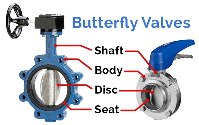
The butterfly valves are commonly used as fire isolation valves. It offers start-stop-regulate flow. Valve is fully open when the disk rotates 90 degrees. The flow is nearly not obscured so that pressure drop is minimal. It is important that the valve should be closed slowly to prevent disk from structural damage and hummering. If there is leakage in the valve, the disk and seat should be examined and cleaned.
Gate Valves
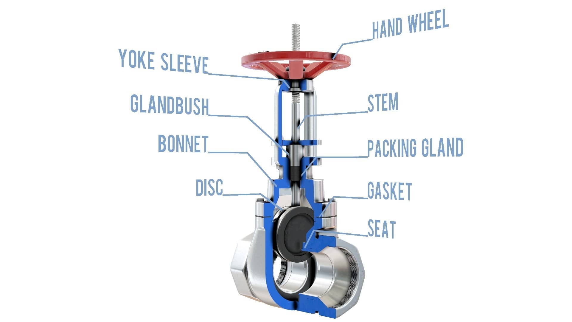
Gate valves are often used as fire isolation valves on board. Gate valves are designed to start-stop the flow, not regulate. This is because when you half open the valve, the fluid passes will not be half of the maximum design of the valve, it will be more than that. This high velocity flow will damage seat and disk. The pressure drop is minimal.
Globe Valve Lapping
Lapping is the process of removing irregularities between metals. Lapping is required on disk or seat of the globe valves if there is a leakage from there. Too much tightening the valve will deepen the irregularity. The process of lapping is as below:
- Check if lapping is required or not.
2. Choose the Lapping Compound
Lapping compound is an abrasive paste that is used to smother the metal surface for mating. They are composed of carborandum, aluminum oxide, silica or silicon carbide. Lapping compounds have grades from extra coarse to extra fine. The coarse compaound smothers surfaces rougly at small grit sizes for rough lapping. The fine compounds have grit size at larger grit sizes for detailed lapping. It is suggested to use lapping paste from coarser to finer.
3. Perform Lapping
Put lapping paste on the seat of the valve or on the lapping plate. Rotate the disk gently at slow angles by slighly pushing.
Continue the same process with finer lapping paste grade.
4. Check the Mating and Test
Check the mating as described 1. If mating is satisfactory, insert back the valve and pressure test.
Rules as per SOLAS II-2/10
- Isolation valves shall be installed for all open deck fire main branches used for purposes other than fire fighting. In ships where deck cargo may be carried, the positions of the hydrants shall be such that they are always readily accessible and the pipes shall be arranged as far as practicable to avoid risk of damage by such cargo.
- The diameter of the fire main and water service pipes shall be sufficient for the effective distribution of the maximum required discharge from two fire pumps operating simultaneously, except that in the case of cargo ships the diameter need only be sufficient for the discharge of 140 m³/h.
- Isolating valves to separate the section of the fire main within the machinery space containing the main fire pump or pumps from the rest of the fire main shall be fitted in an easily accessible and tenable position outside the machinery spaces. The fire main shall be so arranged that when the isolating valves are shut all the hydrants on the ship, except those in the machinery space referred to above, can be supplied with water by another fire pump or an emergency fire pump. The emergency fire pump, its seawater inlet, and suction and delivery pipes and isolating valves shall be located outside the machinery space. If this arrangement cannot be made, the sea-chest may be fitted in the machinery space if the valve is remotely controlled from a position in the same compartment as the emergency fire pump and the suction pipe is as short as practicable. Short lengths of suction or discharge piping may penetrate the machinery space, provided they are enclosed in a substantial steel casing or are insulated to "A-60" class standards. The pipes shall have substantial wall thickness, but in no case less than 11 mm, and shall be welded except for the flanged connection to the sea inlet valve.
- Relief valves shall be provided in conjunction with fire pumps if the pumps are capable of developing a pressure exceeding the design pressure of the water service pipes, hydrants and hoses. These valves shall be so placed and adjusted as to prevent excessive pressure in any part of the fire main system.
- In tankers, isolation valves shall be fitted in the fire main at the poop front in a protected position and on the tank deck at intervals of not more than 40 m to preserve the integrity of the fire main system in case of fire or explosion.
- The number and position of hydrants shall be such that at least two jets of water not emanating from the same hydrant, one of which shall be from a single length of hose, may reach any part of the ship normally accessible to the passengers or crew while the ship is being navigated and any part of any cargo space when empty, any ro-ro space or any vehicle space in which latter case the two jets shall reach any part of the space, each from a single length of hose. Furthermore, such hydrants shall be positioned near the accesses to the protected spaces.
- the following minimum pressures shall be maintained at all hydrants:
4,000 gross tonnage and upwards 0.40 N/mm² (4.0 bar)
less than 4,000 gross tonnage 0.30 N/mm² (3.0 bar)
for cargo ships:
6,000 gross tonnage and upwards 0.27 N/mm² (2.7 bar)
less than 6,000 gross tonnage 0.25 N/mm² (2.5 bar).


